Timer And Contactor R Relay Diagram : Timer Relay Circuit 4 - Wiring Library • Insweb.co - Timers that have only 1 timing mode (for example.
Dapatkan link
Facebook
X
Pinterest
Email
Aplikasi Lainnya
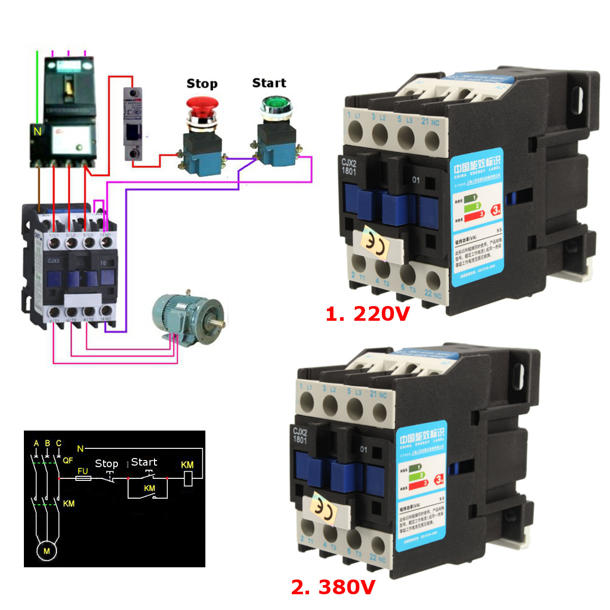
Timer And Contactor R Relay Diagram : Timer Relay Circuit 4 - Wiring Library • Insweb.co - Timers that have only 1 timing mode (for example.. Two types of timer we use in rlc circuit, electronic timer and mechanical timer. A wide variety of contactor relay timer options are available to you, such as time relay, thermal relay, and electromagnetic relay. There are a lot of applications of this ic, mostly used as vibrators like, astable multivibrator, monostable multivibrator, and bistable multivibrator. Timers were used in many applications in our day to day life.one can see the timers in washing machines,micro ovens etc. Nema ratings and test values for dc control circuit contacts.
Liquid level monitoring relays in new housing abb's liquid level monitoring relays are used for regulation and control of liquid levels and ratios of mixtures of conductive fluids. • relays • time relays • monitoring relays • sockets. Electronic relays and controls news. O/l = over load relay. Engineering electrical diagram contactor and timer.
CJX2-1801 AC 220V/380V 18A Contactor Motor Starter Relay 3 ... from img.banggood.com Here i am going to explain about arduino relay timer, which doesn't require any external real time clock module like ds1307. Nema ratings and test values for dc control circuit contacts. Engineering electrical diagram contactor and timer. Disconnect wires leads from terminals 2 and 4 of fan relay cooling and 2 and 4, 5 and 6 of fan relay heating. Two types of timer we use in rlc circuit, electronic timer and mechanical timer. The 555 timer, designed by hans camenzind in 1971. • relays • time relays • monitoring relays • sockets. 555 timer ic is one of the commonly used ic among students and hobbyists.
With help of following timing diagram we can easily understand.
Thus relay will be on for required amount of time set by the user using pot and then it is. 555 timer ic is one of the commonly used ic among students and hobbyists. Vertical power rails and horizontal control rungs. symbols also differ a bit from common electronics notation: You can watch the following video or read the written tutorial below. Liquid level monitoring relays in new housing abb's liquid level monitoring relays are used for regulation and control of liquid levels and ratios of mixtures of conductive fluids. Using an ohmmeter, test between 2 testing compressor contactor. Engineering electrical diagram contactor and timer. There are a lot of applications of this ic, mostly used as vibrators like, astable multivibrator, monostable multivibrator, and bistable multivibrator. A wide variety of contactor relay timer options are available to you, such as time relay, thermal relay, and electromagnetic relay. Relays control one electrical circuit by opening and closing contacts in another circuit. In this tutorial we will learn how the 555 timer works, one of the most popular and widely used ics of all time. Ladder diagrams differ from regular schematic diagrams of the sort common to electronics technicians primarily in the strict orientation of the wiring: The easyrelays combine timers, relays, counters, special functions, inputs and outputs into one compact device that is easily programmed.
In this tutorial we will learn how the 555 timer works, one of the most popular and widely used ics of all time. The lights stay on after parking car, and then. Vertical power rails and horizontal control rungs. symbols also differ a bit from common electronics notation: An iron core is surrounded by a control coil. Technical data data at ta = 25 °c and rated values, unless otherwise indicated.
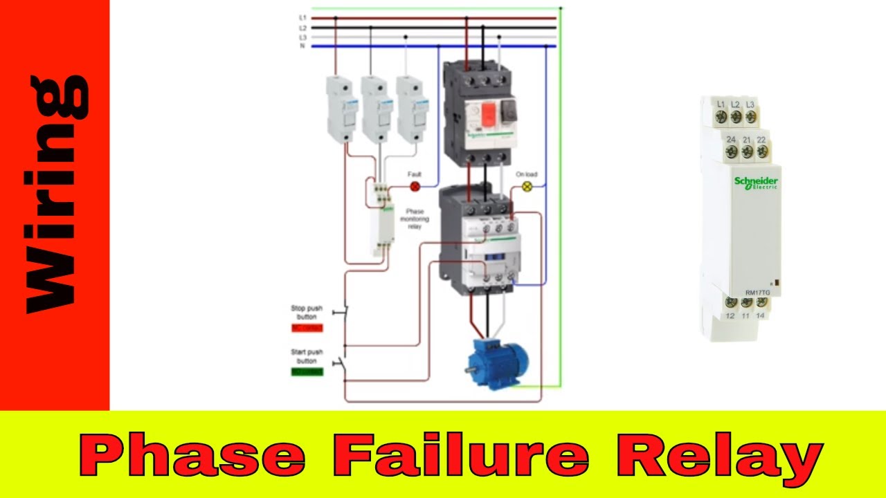
How To Wire Contactors And Relays from i.ytimg.com 555 timer ic is one of the commonly used ic among students and hobbyists. O/l = over load relay. Relays are switches that open and close circuits electromechanically or electronically. Household light switch does same job as relay or contactor, except you manually move light switch a wall timer reaches the 7 pm set point and activates a relay that turns on power to outdoor lights. There are a lot of applications of this ic, mostly used as vibrators like, astable multivibrator, monostable multivibrator, and bistable multivibrator. Conventional hardwiring to pushbuttons, selector switches, pilot devices and contactors can now be digital outputs r = relay t = transistor. Contactors and relays are electric switches. With help of following timing diagram we can easily understand.
Using an ohmmeter, test between 2 testing compressor contactor.
When contactor 1 (c1) is energized, then the two open contact in the line of c1 and c2 will be closed. Timers were used in many applications in our day to day life.one can see the timers in washing machines,micro ovens etc. Time delay relay schematic symbol. Contactors and relays are electric switches. Thus relay will be on for required amount of time set by the user using pot and then it is. • switching capacity available by 10a in spite of small size design for highdensity p.c. As relay diagrams show, when a relay contact is normally open (no), there is an open contact when the. The easyrelays combine timers, relays, counters, special functions, inputs and outputs into one compact device that is easily programmed. Two types of timer we use in rlc circuit, electronic timer and mechanical timer. Relay coils are drawn as circles. Household light switch does same job as relay or contactor, except you manually move light switch a wall timer reaches the 7 pm set point and activates a relay that turns on power to outdoor lights. • selection of plastic material for high temperature and. There are a lot of applications of this ic, mostly used as vibrators like, astable multivibrator, monostable multivibrator, and bistable multivibrator.
When contactor 1 (c1) is energized, then the two open contact in the line of c1 and c2 will be closed. Time delay relay schematic symbol. This is used to control the 'star' contactor. Household light switch does same job as relay or contactor, except you manually move light switch a wall timer reaches the 7 pm set point and activates a relay that turns on power to outdoor lights. Contactor switching time is higher than relay.
Analog Time Switch Fm/1 Quartz Wiring Diagram from wiringall.com • relays • time relays • monitoring relays • sockets. O/l = over load relay. Ladder diagrams differ from regular schematic diagrams of the sort common to electronics technicians primarily in the strict orientation of the wiring: The easyrelays combine timers, relays, counters, special functions, inputs and outputs into one compact device that is easily programmed. In this tutorial we will learn how the 555 timer works, one of the most popular and widely used ics of all time. Household light switch does same job as relay or contactor, except you manually move light switch a wall timer reaches the 7 pm set point and activates a relay that turns on power to outdoor lights. How to contactor with timer wiring diagram and partical. Contactor switching time is higher than relay.
Contactor switching time is higher than relay.
This is used to control the 'star' contactor. Electrical relays and contactors use a low level control signal to switch a much higher voltage or current supply using a numer of different contact arrangements. Relays are switches that open and close circuits electromechanically or electronically. Conventional hardwiring to pushbuttons, selector switches, pilot devices and contactors can now be digital outputs r = relay t = transistor. Yamaha r6 fuse box diagram yamaha rd350 wiring diagram yaesu 8 pin mic wiring yaskawa varispeed f7 wiring diagram yamaha dt250 wiring diagram yamaha rd400 wiring diagram yamaha outboard tachometer wiring diagram xs650 wiring diagram. With help of following timing diagram we can easily understand. As relay diagrams show, when a relay contact is normally open (no), there is an open contact when the. When contactor 1 (c1) is energized, then the two open contact in the line of c1 and c2 will be closed. Disconnect wires leads from terminals 2 and 4 of fan relay cooling and 2 and 4, 5 and 6 of fan relay heating. 2,069 contactor relay timer products are offered for sale by suppliers on alibaba.com, of which relays accounts for 19%, time switches accounts for 1%. Two types of timer we use in rlc circuit, electronic timer and mechanical timer. Timers that have only 1 timing mode (for example. 555 timer ic is one of the commonly used ic among students and hobbyists.
Capricorn Australiamap - Map Of Australia Tropic Of Capricorn - Australia Moment / Things to do near capricorn coast visitor information centre. . Their planetary ruler saturn imbues them. Capricorn park is a park in western australia and has an elevation of 45 metres. From mapcarta, the free map. Search and share any place. The tropic of capricorn passes through 10 countries and one overseas territory. Australia printable, blank maps, outline maps • royalty free. The capricornus bonus map is a reward from entering mojo's into the cauldron of aruba. Cardinal capricorn is the 10th and most paternal of all the signs. Capricornus is among the faintest constellations, just brighter than cancer. Google maps street view of capricorn, new south wales, australia. Map Of Australia Tropic Of Capricorn - Australia Moment from lh6.googleusercontent.com Capric...
Dominik Paris : Dominik Paris Happy With My 6th Place Today Facebook : Dominik paris (sq) esquiador alpino italiano e carabiniere d'italia (es); . Official profile of olympic athlete dominik paris (born 14 apr 1989), including games, medals, results, photos, videos and news. Dominik paris stand mit 18 jahren vor dem nichts. Jump to navigation jump to search. Notizie, foto e video su dominik paris, tutti gli aggiornamenti il messaggero. Dominik paris on wn network delivers the latest videos and editable pages for news & events, including entertainment, music, sports, science and more, sign up and share your playlists. Là où tout le monde s'écroule, l'italien se sublime. Two italians on the podium: See more of dominik paris on facebook. Italský sjezdař dominik paris si při tréninku před závody světového poháru v kitzbühelu přetrhl přední zkřížený vaz v pravém koleni. Dominik paris born april 14 1989 is a world cup alpine ski racer from northern italy ...


Komentar
Posting Komentar